

There is abundant literature describing approaches to radiographic measurement of alignment of the lower limb and the knee. This is timely in the context of the current transition to digital imaging applications and software for taking and recording measurements1–9. It is obviously beneficial to move toward uniformity of methods for defining alignment, and we have supported approaches toward this end10. Yet, while touched on in these and other accounts10–13, limited emphasis has been placed on the importance of limb positioning for radiographic measurements.
Limb positioning is prone to errors that often arise from a lack of standardization, most notably the poor control of limb rotation during patient set-up for imaging. These errors may be exacerbated in the presence of limb deformities, especially those that obscure reference bone landmarks useful in the control of rotation. Therefore, recognition of deformities and control of rotation in the context of both health and disease are important goals for reproducible radiography. Certainly, variations of limb position, especially rotation, significantly influence the alignment measures14,15. The purpose of our editorial is to discuss practical ways to minimize positional errors. This arises from our experience of measurements using a supporting frame to limit positioning variations, thereby improving imaging reliability. Using a positioning frame can limit measurement errors for angles, such as the hip-knee-ankle (HKA) angle, to less than 2° and, with parallax corrected, leg-length distances within 2 mm14.
Alignment and limitation of positional error
Long radiographic views of the whole limb in stance are ideal for measuring alignment of the knee, in terms of both the HKA angle and the other joint angles that may contribute to any deformity (Figure 1). In practice, femorotibial alignment is commonly assessed from short views of the knee (Figure 1, hatched area) from which the anatomic (shaft) axes of the femur and tibia (FS, TS) may be located. The femoral mechanical (FM) axis is not available from these views, but may be approximated since FS and FM have a conservative angular offset from each other (about 4°–5°, with low variance)15–20. Correlations (r) between the femorotibial angle from knee radiographs and the mechanical axis angle obtained from full-limb radiographs are reported to range from 0.65 to 0.8817,18,21. Thus, the estimation of FM from short views may be described as useful rather than definitive in terms of revealing the mechanical alignment. Although the femorotibial angle is sensitive and specific enough to differentiate varus and valgus knee alignment in most cases17, in limbs with proximal or distal bone deformity predictions from truncated views are likely not reliable11,12. It is self-evident that the shorter the view of the knee the greater the chance of missing such deformities, and with that the greater risk of ending up with faulty limb alignment parameters. It is unfortunate that the prevalence of such deformities, and hence the associated error risk, is not well documented. While error analyses have been undertaken for alignment measures obtained from long-limb images using a positioning frame14, we are unaware of any similar evaluation for more limited views of the limb. All this points to the need for surveys of alignment data comparing shortlength with full-length radiographs11,12,22,23.

The angles that portray knee alignment (modified from Cooke, et al10). The rectangular hatched region illustrates the limitations imposed on angular measurements of limb alignment when a short view of the knee is obtained. The tibial mechanical (TM) axis and the anatomic tibial shaft (TS) axis are typically coincident. However, the femoral mechanical (FM) axis and the anatomic femoral shaft (FS) axis are not coincident, although the angle between them (FM-FS angle) is generally conserved at 4°–5°. This means that, in the event FM and TM cannot be located from radiographs (e.g., short views), the hip-knee-ankle angle (HKA or FM-TM) can be approximated from the measured FS-TS angle by correcting for an assumed angular offset of 4°–5°. LBA: load-bearing axis; CH: condylarhip angle: the angle of the femoral condylar tangent with respect to the femoral mechanical axis, varus negative, valgus positive; PA: plateau-ankle angle: the angle between the tibial margin tangent and the tibial mechanical axis, varus negative, valgus positive; CP: condylar-plateau angle: the angle between the femoral and tibial joint surface tangents, narrowing medially negative and laterally positive; HKA: hip-knee-ankle angle: the angle between the femoral and tibial mechanical axes, varus negative, valgus positive; FM: femoral mechanical axis; TM: tibial mechanical axis; FS: femoral shaft axis; TS: tibial shaft axis; FM-FS: angle between the femoral mechanical axis and the femoral shaft axis.
Toward the reproducibility of alignment data through adequate control of positional error, long-limb views have the advantage of locating hip, knee, and ankle positions. From these may be computed the mechanical axes of the limb. Integral to this approach, we use a frame/platform structure to standardize placement of the entire limb including the measurement of foot rotation angles. Since the platform turns, the patient may be rotated 90° between frontal and lateral views without upset of positioning11,13,14. Using such a system our general approach is to start with the patient’s ankles set over fixed marks on the platform: the heels are place on sagittal lines spaced 6 inches apart. Technologists are trained to flex each limb in turn, rotating the limb to bring the plane of knee flexion within the sagittal plane (Figure 2). Foot rotation angles are then recorded as degrees of deviation of the second toe from the center (sagittal) line. For this purpose there is a reference template on the platform11 (Figure 3). Images are generally obtained with the knee extended, but Sanfridsson, et al15 have shown that controlled semiflexed views can be obtained using the frame. In an analysis of HKA and femoral shaft-tibial shaft (FS-TS) angle measurements in healthy volunteers15, the authors found differences of less than 1° between the semiflexed and extended positions attributable to femorotibial rotation. The varus angle was decreased in extension compared to semiflexion.

A standardized imaging frame and the set-up used to obtain reliable limb positioning. The technologist is shown evaluating the direction of the knee flexion plane.
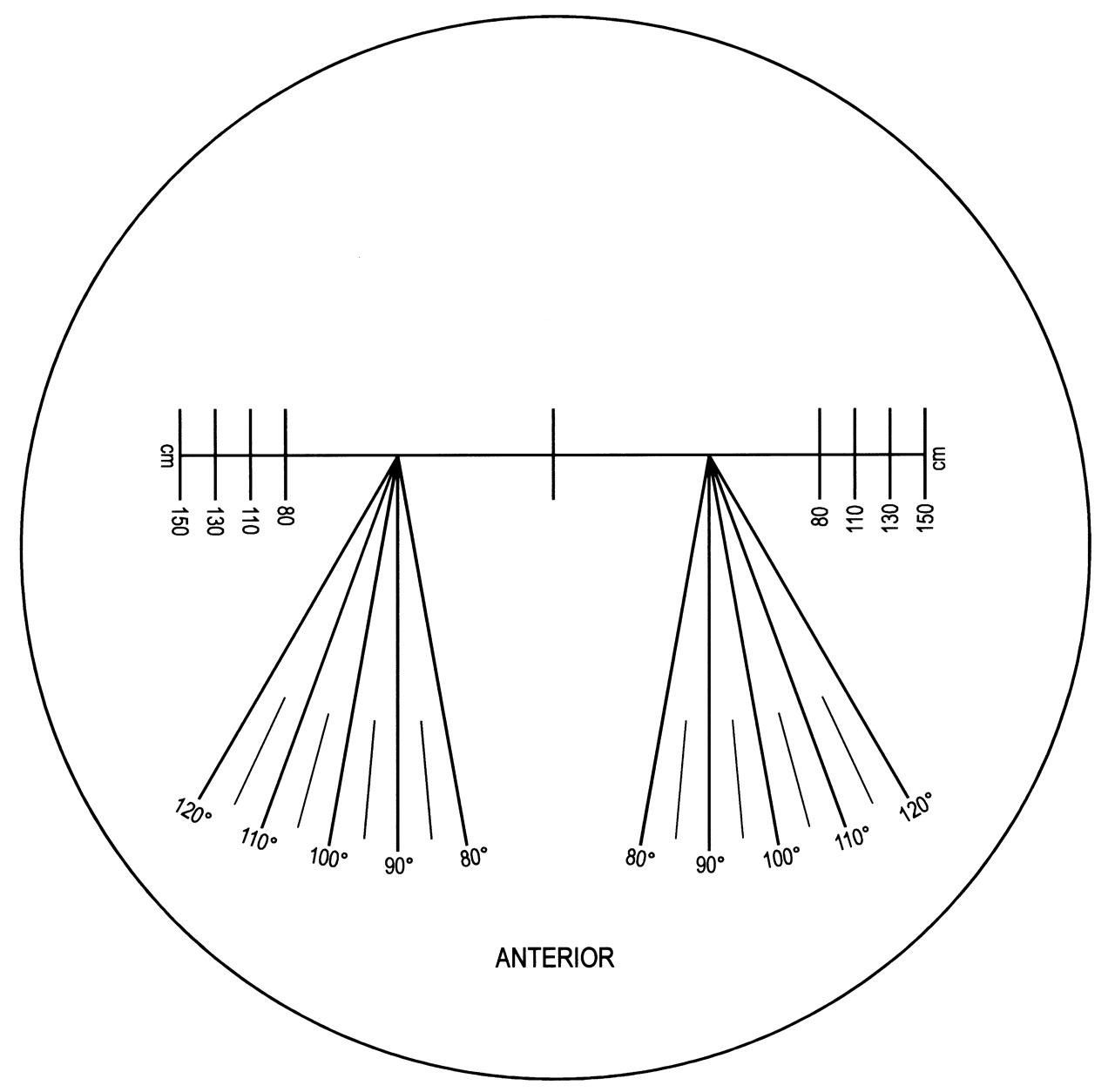
Example of a positioning decal used to locate the feet and record foot rotation. Both limbs are set up with equal weight and each knee flexion plane ahead. The feet are positioned with the heels on their respective sagittal lines spaced 6 inches apart. After rotating the knees to correctly align the flexion plane, foot rotation is recorded as degrees of deviation of the second toe from the center (sagittal) line.
To optimally align the limb the orientation of the patella is not the prime consideration, since patellar malalignment is quite common in arthritic knees, especially in the presence of varus deformity24. In such knees, to align the patella in the forward-pointing position is to put the flexion angle outside of the sagittal plane25, and a commonly associated lateral shift in the location of the tibial tubercle reduces the reliability of this landmark as a positional reference24,25. Similarly, fixed foot rotation is not a reliable consideration in positioning. When foot rotation is fixed (e.g., 10° of external rotation using the Synarc frame), there is the likelihood of malrotating the limb should there be excessive external or internal tibial torsion26. Finally, we refer to the common practice of positioning according to the colinearity of the posterior profiles of the femoral condyles27. This approach is also one that we do not favor, since condylar asymmetry tends to be exaggerated in individuals with knee osteoarthritis28–30.
As a basis for control of positioning, alignment of the limb according to the orientation of the knee flexion plane lends itself naturally to reproducibility. When the knee is moved through some degree of flexion, the lower leg tracks around the condyles on the knee’s flexion axis (an orientation well approximated to the transepicondylar line)20,28–31 and perpendicular to the flexion plane.
Healthy limbs are remarkably symmetrical, and with the frame/platform assembly both knees may be imaged simultaneously, with cassettes positioned to the rear, preferably for hips and ankles as well. In situations where the limbs are very deformed (e.g., severe varus or valgus deformities or in the rarer case of a “windswept deformity”), it is better to use a separate image for each limb. Asymmetric rotational malalignments of the tibia may require positioning such that each foot has a different degree of rotation in order to bring the flexion plane into coincidence with the sagittal plane. In contrast, proximal femoral rotational variations (anteversion or retroversion) do not influence foot positioning, which depends on rotation alignment only at the distal end of the femur as the technologist rotates the knee to bring the flexion plane into the desired orientation. Femoral ante/retroversion may, however, be reflected in small changes in the measured femoral anatomic and mechanical axis angles.
Even without a positioning frame, these principles for controlling positional errors may be successfully adapted to other radiographic configurations to yield a reduction of positional errors.
Recognizing limb deformity and positional error
Technologists need to acquire the skills not only to control against positional errors, but also to recognize malpositioning when reading radiographic knee images. Considering a knee with mild medial compartment osteoarthritis, if it is correctly aligned in the frame the image will show symmetry of the femoral condylar outlines and of the femoral intercondylar notch viewed frontally (Figure 4a). On the frontal view the tibiofibular gap is also evident, with the proximal tibiofibular joint partly covered by the lateral tibial margin. The outline of the patella is usually central. In the orthogonal lateral view the femoral condyles overlap and the medial articular surface (slightly larger than the lateral) is typically more distal and posterior to the lateral surface (Figure 4b). The fibular shaft is evident posteriorly, slightly separated from the posterior tibial shaft, with the tibiofibular joint overlapped by the proximal posterior tibia.

A. Anterior-posterior standing view of a knee with mild medial compartment osteoarthritis. Note the condylar symmetry of the femoral condylar projections and the intercondylar notch. A distinct tibiofibular interval is present, with slight overlap of the proximal tibiofibular joint. B. The same knee viewed standing from the 90° lateral perspective. Note the asymmetry of the femoral condylar projections, with the medial surface being more distal and posterior. Note the slim tibiofibular gap.
In the same knee that has been positioned with excessive external rotation, the frontal view reveals the medial femoral condyle to have become more prominent while the lateral femoral condyle becomes more vertical (Figure 5a). The femoral notch is now asymmetric, with the lateral wall of the notch more vertical. The tibiofibular interval is narrow and the joint more covered. The patella has moved to a more lateral position. Conversely, in a knee positioned with too much internal rotation (Figure 5b), the opposite applies.

A. In this view the same knee (Figure 4) has been repositioned in the frame with a small degree of external rotation. Note the prominence of the medial femoral condyle and the asymmetry of the intercondylar notch. The patella is seen more lateral to the midline. Note narrowing of the tibiofibular interval with more overlap of the proximal tibiofibular joint. B. The same knee viewed from the front, but repositioned with some internal rotation. Note the more medially disposed patella, the greater prominence of the lateral femoral condyle, the asymmetry of the intercondylar notch, and the widened tibiofibular interval.
While the illustrations used here are of a knee that is not severely affected by osteoarthritis, the same features are evident in those with more advanced arthritis when malpositioned.
Summary
Standard, accurate, and reliable measurements of knee alignment, while desirable, are too frequently unavailable. The main drawbacks are the diversity of methods for imaging measurements and the variety of imaging set-ups in which imaging error is unknown or not well defined. It is obviously desirable to work toward uniformity in these areas. Regarding radiographic configurations, short views are commonly used, but fail to locate the mechanical axes (at least directly), which is a limitation that becomes serious in the presence of many limb deformities. Long views overcome these limitations, providing locations for the hip, knee, and ankle centers from which the limb mechanical axes, along with the orientations of the knee’s articulating surfaces, may be computed.
Whatever methods are used, there is a universal requirement to reduce errors by control of positioning, and we have described our use of a special frame to this end. The basic approach to positioning is important and we have outlined a procedure where the knee’s plane of flexion is the common reference for positioning, specifically to align it within the sagittal plane. We have discussed our reasons, notably heightened risk of error in the presence of deformities, for distrusting the use of other positioning guides that include positioning the limbs according to the orientation of the patella, tibial tubercle, foot, and condylar outlines. Finally, the importance of technologist training has been emphasized, in the context of correct positioning of patients, and in identification of (and compensation for) mal-rotation errors in the radiographic images. Thus, as in every field, training and experience are both critical elements of good radiography.
Acknowledgments
The editorial assistance of Dr. Allan Scudamore during the preparation of the manuscript is gratefully acknowledged.


